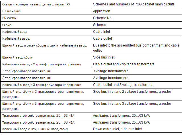
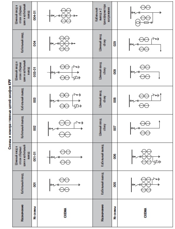
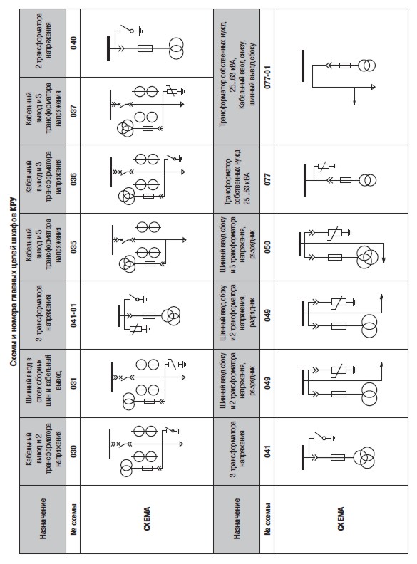
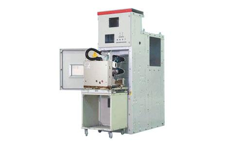
Package switchgears (PSG) KRU K 10 for current up to 2000A
Application and designated areas
Package switchgears of series PSG KRU K 10 with inner installation in a metal casing is of two-side service with medium switch position and complies with GOST 14693-90, IEC 62271-200 and are intended to package high-voltage switchgears PSG 10 kV of three-phase current with frequency of 50 Hz and rated voltage of 10 kV for nets with an isolated neutral conductor.
Package switchgears of series KRU К 10 manufactured by «ELECTRO GROUP» («ЭЛЕКТРО ГРУП») have competitive advantages in reliability and safety, flexibility and efficiency.
PSG К 10 are packaged with vacuum and SF-6 breakers BB TEL, SION, EVOLIS, VD4 and modern microprocessor relay protection devices.
Application of bolting connections in manufacturing switchgear cabinets of assembled metal constructions allows one to:
– increase anti-corrosion stability by means of a small amount of welded joints;
– provide reliable grounding of metal construction;
– provide comfort repair and easy access to switchgear cabinet compartments;
– both single-side and two-side switchgear cabinet service is provided;
– access to the cable compartment is provided without breaker roll-out from a switchgear cabinet;
– breaker roll-in – roll-out from working into control position and back is provided with a closed compartment door of a breaker with a worm gear by means of a take-off handle;
– possible installation of two roll-out elements in a single cabinet: vacuum breaker in a breaker compartment and a voltage measuring transformer in a cable compartment of a switchgear cabinet;
– possible mechanical blocking of a cable connection compartment door and a grounding breaker;
– mechanical blocking of a back cover of a switchgear cabinet and a grounding breaker;
– full PSG set delivery for needs of substation (switchgear cabinets, busbar bridges, bus inlet, cabinets with auxiliaries transformers, etc).
Type of main cabinets depending on built-in controls:
– with high voltage breakers;
– with load breakers;
– with load breakers;
– with arresters or surge arresters;
– with voltage transformers;
– with current transformers;
– with cable assemblies;
– with power transformers;
– combined (e.g. with voltage transformers and arresters, with breakers and current transformers);
– with power fuse.
The following relay protection and emergency controls can be applied to a KRU switchgear cabinet:
– electromechanical controls and electronic static devices of type RS, RT (РС, РТ);
– package microprocessor devices of type REF, SEPAM, SРАС, BMRZ (БМРЗ), TEMP (ТЕМП), Sirius (Сириус), TOR (ТОР), etc. with possible registering and transfer of events as well as current and voltage parameters by Modbus port in an APCS (automatic power control system) and APSCMS (automatic power supply and control monitoring system).
Structure of symbolic designation
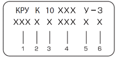
1 – package switchgear;
2 – switchgear cabinet with a cassette unit;
3 – voltage class10kV4 – scheme number (Annex 1);
5 – climatic category according to GOST 15150;
6 – placement category according to GOST 15150;
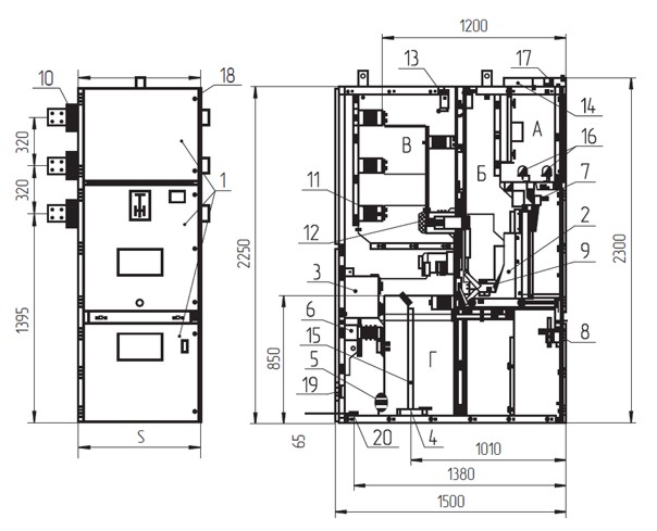
Cabinet with a roll-out element for rated current up to 2000A
А – relay compartment; B – roll-out element compartment; C – assembled bus compartment; D – inlet-outlet compartment.
1 – compartment doors; 2 – cassette roll-out element; 3 – current transformer; 4 – zero-sequence current transformer; 5 – surge arrester; 6 – grounding blades node; 7 – mechanism of secondary connection blocking; 8 – blocking mechanism of inlet-outlet compartment door; 9 – shutter mechanism; 10 – bushing insulator; 11 – supporting insulator; 12 – bushing insulator under fixed contact; 13 – arch protection of valves;14 – control cables tray; 15 – power cable; 16 – terminal block;17 – terminal block of operation ties;18 – locking arrangement; 19 – lighting block; 20 – grounding bus.
PSG STRUCTURE
PSG KRU is a set of separate cabinets with assembled buses in the cabinet upper part, with commutation units, measuring devices, control and alarming devices, protection devices for compartments of PSG cabinets from open electric arcs. Arc protection of PSG cabinet compartments may be of valve type based on electromechanical elements or light-activated silicon switches, optical devices «Ovod» («Овод»), REA, ERS and BKO (БКО).
PSG delivery package includes:
– PSG cabinet, busbar bridges, bus units, bus bars (electrical wires) according to the specification (specifications data sheets);
– parts for PSG assembling (bus strips, bus ties, etc) according to the project and factory WCD;
– kit of fixing hardware for bolt connections of assembled buses, etc.
– components transported in a separate packing (assembled buses, take off parts, hardware);
– service documentation according to the list of service documents;
– kits of spare parts tools and accessories and its supply are specified in the Agreement.
Note. PSG delivery package may also include:
– power supply cabinet (PSC);
– central alarm cabinet (CAC),
– heating cabinets (HC), arcing fault protection cabinets etc in an add-on hardware,
– transfer cabinets for connection to PSGs of other series;
– cabinets with auxiliaries transformers of power up to 40 kVA.
Service documentation (SD) to a PSG kit includes:
– PSG certificates of conformity with a seal of the manufacturer – 1;
– PSG operation manual – 1;
– PSG section assembled drawings – 1;
– main electrical schemes of auxiliary circuits – 1;
– commutation controls specification;
– service documentation for main controls, if TU specifications are not provided in the SD – 1.
Tools and accessory kit includes:
– take-off handle to move the roll-out element from one fixed position into another. One kit is supplied for five and less cabinets in a single order or three kits for a substation;
– locking and unlocking keys to doors of relay compartment, roll-out element compartment and cable compartment;
– one take-off lever (Annex 2, fig. 36) operating with a line bus grounder is supplied for five or less cabinets which are separately supplied, but not more than two for a substation;
– transport trolley to roll-out from roll-out elements. One trolley of every kind is supplied for a cabinet section.
Main schemes of auxiliary electrical circuits
Schemes of auxiliary circuits can be based on alternating and direct (rectified) operation current for 220 and 110 V.
Construction of main electrical schemes is made by a modular type, i.e. schemes have constant (permanent part) and additional circuits – scheme variants (changing part).
Additional circuits include:
– current protections from inter-phase short circuits (different variants);
– protection from grounding;
– circuits of commercial and technical counters of electric energy;
– other pieces (start of overcurrent protection, control buttons etc);
– operation electromagnetic blocking;
– current, voltage and power converter, arch fault protection schemes.
Electrical connection of roll-out elements and relay cabinets is made by means of one or two plug connections with movable parts fixed on ends of wrap hoses and movable are on the bottom of relay compartment of a PSG cabinet to enable an easy substitute for a new type of breaker with no re-install of auxiliary cabinet circuits.
Factory schemes of auxiliary circuits by their application are developed for lead-in switchgear cabinets, section breakers, section interrupters, voltage transformers, auxiliaries transformers, lines outgoing to GBC, auxiliaries transformers.
Side panels supplied with PSG are fitted for schemes of general station application of transformer control schemes, system of rectified current supply, AFL, bus protection, lead-in supply of operation ties, schemes of general station AFP etc.
Schemes of general station application can be also applied in relay compartments of section breakers, power fuses, cable assemblies.
Factory schemes of auxiliary circuits are developed in two variants:
– based on electromechanical relays;
– based on microprocessor relay protection and control devices.
Power account circuits can be based on induction electronic counters or multifunctional microprocessor counters of domestic or foreign manufacture.
PSG cabinets of domestic manufacture are parts of package switchgear represented by a set of cabinets interconnected within a section (see figure 1).
PSG may consist of bus bridges between two rows of transformers, bus inlets and hanging relay cabinets (see figure 1).
PSG cabinet is a stiff assembled metal construction (casing) with built-in devices and controls of main circuit with elements of electrical connections (conductor buses). Upper part of every PSG contains all required relay protection equipment, automatics, metering, alarming controls and secondary circuits in a separate insulated compartment (hereinafter referred to as a relay compartment.
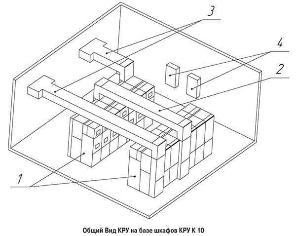
PSG configuration based on PSG K 10 cabinets
1 – Section of PSG cabinets; 2 – Bus bridge; 3 – Bus inlets; 4 – Hanging relay cabinets
Every PSG cabinet has a roll-out truck (roll-out element) equipped with some controls (depending on a scheme of main circuit) such as vacuum breakers, voltage transformers, fuses, bus breakers.
Casing of a PSG cabinet has a shutter mechanism to ground a breaker and blocking devices. There are main circuit contacts fixed in the cabinet casing.
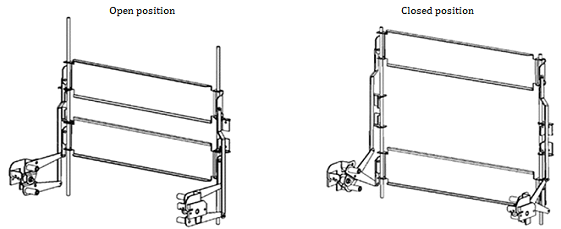
A roll-out element is located in the medium part of a cabinet and it may be in the following positions relative to the casing:
– operating;
– control;
– maintenance.
Operating position is an extreme rolled-in position of a roll-out element (RE). In operating position, separable joints of main and auxiliary circuits are closed and the roll-out element is fully connected to perform its functions. RE operating position is fixed and the breaker can be switched on in this position.
Control position is an extreme rolled-out position of a roll-out element (RE) when main circuit contacts are broken, contacts of auxiliary circuits are connected and enable testing of roll-out elements and auxiliary circuits testing. RE control position is not fixed either. Opening of RE compartment door may be performed only in this extreme rolled-out position as well as breaker switching on.
Maintenance position is a position when a roll-out element is fully extracted from a cabinet casing, contacts of main and auxiliary circuits are open and the roll-out element can be subject to inspection and maintenance.
Cabinet casing is a riveted bolted construction of zinced steel some 2-3 mm thick divided by baffles into 4 insulated plated compartments.
– Relay compartment – А
– Roll-out element compartment – B
– Assembled bus compartment – C
– Inlet-outlet compartment – D
Cabinet casing is equipped with the following main mechanisms:
– shutter mechanism to close fixed main circuit contacts when a roll-out element is in a control or maintenance positions;
– grounding breaker and mechanism of grounding breaker control to enable grounding of an open part of main circuit;
– mechanism of roll-out element blocking when a rolled-out element compartment door is open.
Grounding breaker
For secure PSG maintenance, line bus compartment is equipped with a grounding breaker. The grounder consists of a grounding blades unit where all elements are fixed to a rigid frame. The grounder is activated by a handle of the spare parts kit and handle turning load is transmitted by means of drive facing the facade cabinet panel to the grounding blades unit.
PSG cabinets are equipped with line bus grounders and perform blocking that prevents:
– roll-in of roll-out element into operating position with switched grounder position;
– grounder switching in case when roll-out element is in an operating position.
For this purpose, actuator driving shaft is connected with a lever and a system of blockings.
Roll-out elements
Roll-out elements
Roll-out elements of PSG cabinets represent an assembled welded construction on rollers with mounted various controls depending on the type of cabinet (breakers, voltage transformers, auxiliaries transformers etc).
Roll-out elements (RE) are performed in hardware:
– RE with a vacuum breaker;
– RE with a bus breaker;
– RE with voltage transformers;
– RE with auxiliaries transformers.
Roll-out element in a PSG cabinet has two fixed positions: operating and control.
Roll-out element in the operating position is in a cabinet casing and main and auxiliary circuits are attached. Control position of roll-out element is in a cabinet casing when main circuits are open, blades and sockets of separable connections are at a safe (in regard of electric breakdown) distance from each other. In this case auxiliary circuits are closed and socket connections of auxiliary circuits are in a jointed condition.
To provide electric contact of roll-out element with a cabinet casing, the roll-out element is equipped with a grounding blade sliding along the grounding bus set on the bottom of breaker compartment in a PSG cabinet.
Descriptions of breakers are provided in manuals accompanying these breakers.
Movement of roll-out element from a control position into operating position and back are made manually with a worm gear (lead screw).
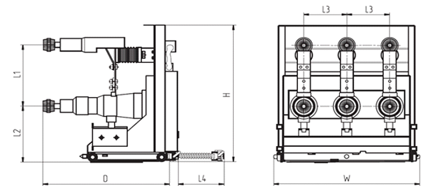
Roll-out element with vacuum breakers of KVE (КВЭ) / TEL for rated currents of 630, 1000A
Transport trolley of roll-out element
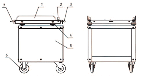
1 – base, 2 – thrust, 3 – handle, 4 – control screw pair, 5 – frame, 6 – wheels, 7 – guides.
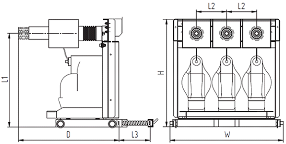
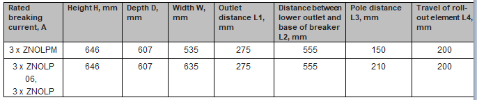
Roll-out element with voltage transformers 3 x ZNOLP (ЗНОЛП)
Blockings
To prevent wrong operation of PSG cabinets, the following blockings are provided:
– mechanical;
– electromechanical.
Mechanical blocking does not provide for:
– movement of roll-out element from operating position into control position and back with a switched vacuum breaker;
– grounding blade switching in a PSG cabinet when a roll-out element is in operating position;
– roll-in of roll-out element in a switched position of a grounding breaker;
– movement of roll-out element with an open door of roll-out element compartment.
Electromagnetic blocking does not provide for:
– vacuum breaker switching in an intermediate position between operating and control positions of roll-out element;
– vacuum breaker switching with switched grounding blades;
– voltage supply to grounded bus sections.
In addition to blockings according to electrical safety rules for a safe PSG servicing, additional blockings that prevent opening of a door of a line cabinet compartment and removal of back cabinet wall is provided when grounding blades are open.
A blocking which prevents movement of a roll-out element from working position into control position and back with a switched breaker is made automatically.
Control and operating positions of roll-out element are signaled with help of auxiliary terminal switches which actuate in working and control positions.
A blocking which does not allow breaker switching in an intermediate position between operating and control positions of roll-out element is made in electromagnetic form. When a breaker moves between operating and control positions, a terminal breaking unit which is connected with rods opens circuits of breaker switching.
A blocking which does not allow voltage supply to grounded buses is made in electromagnetic hardware. An electromagnet located on a base of a roll-out trolley with a bus breaker blocks movement of a roll-out element from control position into operating position and back to supply voltage by means of an electric signal from operative blocking circuits.